
3-D industrial cone-beam computed tomography (CBCT) using flat panel imagers has become a powerful tool for applications like dimensional metrology, non-destructive testing, defect identification, and general quality control. One of CBCT’s unique advantages is that it allows for the entire volume to be scanned in a single rotation thus greatly increasing throughput. However, the wide-area cone-beam beam generates a large amount of scattered radiation that, if not corrected for, produces images that suffer from artifacts such as cupping, shading, streaks, false inhomogeneities, and quantification inaccuracies. To solve these issues, our team here at Varex Imaging is developing 3D VSHARP, a next generation CBCT scatter correction algorithm that quickly calculates the photon transport through a first-pass CBCT volume model and separately estimates the primary photons and scattered photons arriving in the panel detector. 3D VSHARP then uses this information to remove the estimated scattered signal from the original projections. By coupling a fast finite-element deterministic photon transport solver with an NVidia GPU, our aim is to greatly improve the quality of industrial CBCT while maintaining reconstruction speeds that are fast enough to open up the possibility of using CBCT for parts inspection on an assembly line.
I will be presenting the results of our first demonstrations of 3D VSHARP on aluminium and Inconel parts at the 9th International Conference on Industrial Computed Tomography held 13-15 February 2019 in Padova, Italy. This is an event organised by the University of Padova in collaboration with the University of Applied Sciences Upper Austria and will be attended by industry and academic experts in the field of Industrial CT. Our paper is titled ‘Scatter Correction for Industrial Cone-Beam Computed Tomography (CBCT) Using 3D VSHARP, a fast GPU-Based Linear Boltzmann Transport Equation Solver.”
The development of 3D VSHARP originated with medical CBCT work at Varian Medical Systems, Varex Imaging’s former parent company, and has been extended to industrial applications by collaboration between Varian and Varex Imaging teams. The Varex Imaging team includes: Josh Star-Lack, Kevin Holt, Martin Hu, Steve Hoelzer, Sungwon Yoon, Eugeny Sosnovsky, Gregory Failla, David Nisius. In my role as a Varex Imaging Scientist with a Ph.D. in Nuclear Engineering I was able to leverage my expertise in radiation detector systems and physics simulation to help validate the accuracy of 3D VSHARP and implement new detector response models for higher energy x-ray sources.
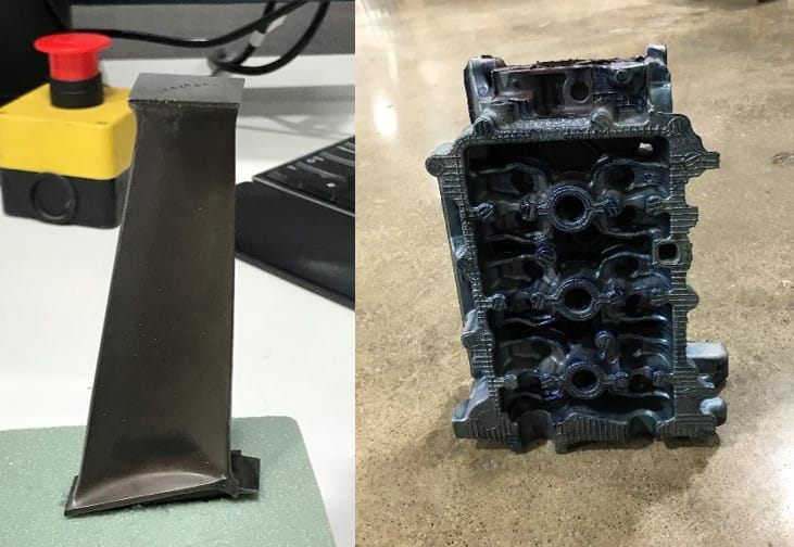
To experimentally verify the new 3D VSHARP scatter-correction tool, we looked at industrial CBCT scans of an aluminum motorcycle cylinder head and a small Inconel turbine blade, performed at 450kV. The scans were taken on a Varex Imaging Scanning Services (https://www.vareximaging.com/products/security-industrial/industrial-ct-scanning-services) 450 kV system using a 1620-AN3 panel which has an active area of 41cm x41cm and a 200µm pixel pitch. The scanned objects are shown in Figure 1.
The results from this preliminary study are very encouraging as described below:
Aluminum Motorcycle Cylinder Head Example
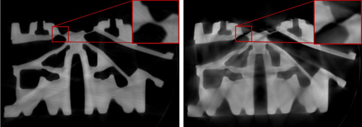
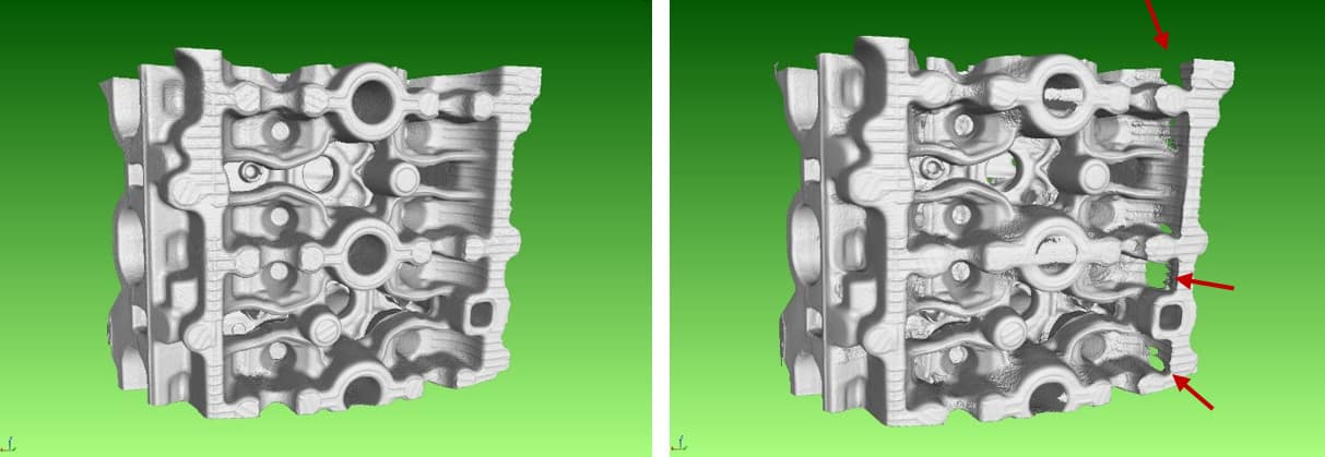
Figure 2 shows a central axial slice of both a 3D VSHARP-corrected and a non-scatter-corrected volume. As can be seen, the 3D VSHARP reconstruction is crisper and has improved material homogeneity. The red box outlines a zoomed-in region where a thin aluminum wall is only visible following scatter correction. When the CBCT volumes are rendered in VG Studio (Volume Graphics, Heidelberg, Germany), we see improved surface definition following 3D VSHARP scatter correction reflecting the improvement in the material uniformity (Figure 3). Artifactual holes appear in the side walls of the uncorrected volume when none are, in fact, present.
For more results and a deeper explanation of the algorithm, download our white paper here where you can also see the results of our Inconel turbine blade reconstruction. The algorithm is currently being incorporated into Varex Imaging’s Cone Beam Software Toolset (CST) where it will undergo extensive testing in preparation for a beta release targeted towards the end of FY ’19.


